Strain wave gearing is known for its near zero backlash, compact design and axial construction. However it is not known for being cheap. This is why Simon Merrett created waves (pun fully intended) with his DIY 3D printed strain wave gear reduction first shown on hackaday in 2017.
In this post I show how to recreate this design in Fusion 360 along with a few improvements like the use of a proper flex spline cup. Such a design could be idea for robotics applications or things like a 4th axis on a milling machine.

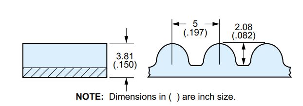
The belt I have chosen for the flex spline is a 50T HTD 5M (5mm pitch) belt turned inside out. As discussed in a previous post this belt has the following parameters:
- Thickness of 3.81 mm
- Tooth height of 2.08 mm
- 5mm pitch
- 3.05 mm radius on the teeth and 1.49 mm radius on the base of the teeth.
The pitch diameter of a belt is the diameter of the belt as measured at the reinforcing steel wire. To estimate the pitch diameter of this belt you just calculate the circumference (50 teeth * 5 mm pitch = 250 mm) and divide by pi (250mm / pi = 79.58 mm). When we turn the belt inside out (invert it) this length should remain the same due to the steel wire. The rest of the belt however will become compressed/stretched to accommodate the new shape. Thanks to this this handy timing pulley diameter calculator created by droftarts on his parametric pulley page we can see that the pitch line offset for a HTD 5M belt is 0.5715 mm. That is the distance from the pitch diameter to the base of the tooth. This distance will be the same when the belt is inverted and so we now know the distance to the base of the tooth will be:
Diameter for base of tooth for an inverted belt = pitch diameter + 2 * pitch offset
Diameter for base of tooth for an inverted belt = 79.58 + 2 * 0.5715 = 80.723 mm
With that piece of key information we can now model the inverted belt in the same way as you would a normal pulley
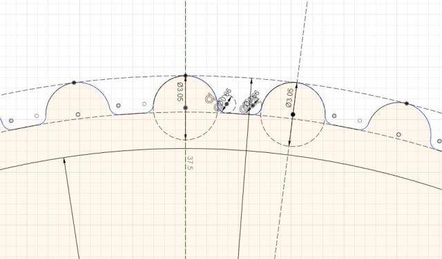
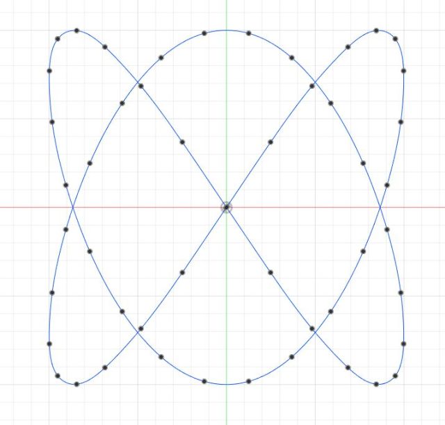
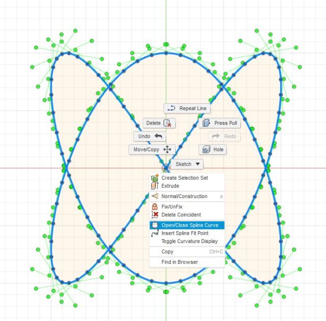
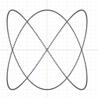
One assumption that I made with this belt is that the majority of the flex occurs in the valleys rather than the teeth and so I have modelled the belt accordingly. This involved generating 3.05 mm teeth diameter spaced 7.2 degrees apart with the valley distance increased to make up the gap. For comparison the image below is of a the same belt but not inverted. Notice that the valleys are slightly different in size.
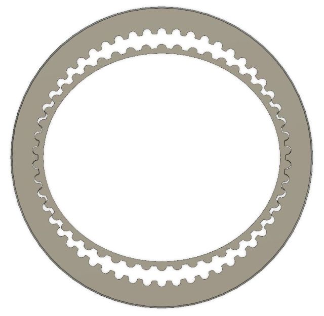
With the inverse belt design its time to move onto the circular spline. The construction of the circular spline is exactly the same as the inverse belt discussed above with the exception that the grooves are concave and facing inwards. For the circular spline I have selected 54 grooves for a gear ration of 12.5:1 (50 / (54 – 50) = 12.5 : 1).

Its clear from the image above that the inner inverted belt (flexible spline) and the outer ring (circular spline) are not touching. This is because the flexible spline has not been deformed by a wave generator.
To determine the correct shape of the wave generator and thus the scaling of our flex spline in two dimensions we can consult this ellipse calculator. I used the base of the teeth for reference of the starting circle and the matching base in the outer ring for the widest diameter after deforming. The spreadsheet just estimates the minor axis of an ellipse that maintains the same area as the starting circle and displays the required scaling for the flexible spline. Once applied to the flexible spline it now meshes with the circular spline.
Moving on to the flex spline cup. This component will need to be attached to the flex spline belt by some means, possibly a flexible glue. The flex spline cup acts to hold the flex spline belt in place and stop it from rotating and thereby allowing it to do usable work to the circular spline. This cup was generated by creating a circle a desired distance below the deformed flex spline belt and then using the loft feature to generate the geometry. Note that you will need to loft a solid body first then create an offset top and bottom to loft cut out the middle.
This cup would be the trickiest thing to make for a DIY construction. If possible, an off the shelf cup (a literal drinking cup) made of stainless steel or similar could work well. Shout-out to the Dexter guys for that idea which they use on their robot arm.
Finally we come to the wave generator. The is the component that is connected to your motor and that deforms the flex spline. Rather than bearings in a cage like the commercial design I have oped for for the easier to construct ball bearing approach.
686ZZ Bearings are attached to a plate by M6 bolts and lock nuts. These bearings are arranged so that they maintain the correct ellipse shape of the spline. The position of the bearings was estimated by just offsetting the inner section of the ellipse by the diameter of the bearings plus the thickness of the flex spline cup wall.
Lastly we need a bearing surface with pre-load to hold the output circular spline. Large 6820 sized bearings could work well that regards but I have yet to include them in the model.
More to come.