
Below I outline three separate concepts for moving in the X and Y plane with a specific emphasis on minimising the moving mass, maintaining high mechanical stiffness, reducing backlash and allowing two stepper motors to work in tandem. It is my hope that these concepts, or some variation of them, will make high accelerations possible in the X/Y plane without sacrificing positional accuracy.
Note: If anyone is aware of what the correct names are for these types of designs then please let me know by leaving a comment.
TandemA (Kite)
This first concept relies on the movement of two rods, jointed at an elbow by a bearing, having only four degrees of freedom: Translation forward and backwards and rotational yaw left and right. This movement style is inspired by polargraph drawing machines, but can also be thought of as one third of a Stewart platform.

An example of the movement available with this setup is shown in the video below which was made using Sketchup with the aid of the sketchyphysics plugin.
The build area (the area swept by the elbow where a tool would sit) is shown by the red filled section in the image above and has a shape that resembles a kite. The movement is brought about by the rotation of a gear on either of the two stationary stepper motors which pushes the a rod towards or away from a pivot point using a gear rack as shown by this close up image. If one rod is extended or retracted more than the other then this results in sideways movement or if both rods are extended or contracted together this a forward or backwards movement.
Advantages of TandemA
- Like the CoreXY or Delta design, both motors can work in tandem to move the elbow joint in the conventional X/Y-axis directions. Only a specific movement through a given arc will use a single motor. In this case the shape of such an arc will be similar to the build area boundaries.
- A high stiffness, low backlash mechanical arrangement should aid in maintaining accurate movements even with high acceleration.
- The total moving mass for both axis is comprised of only the two rods with attached gear racks, one bearing and the tool of your choice (hot end, laser etc). This low moving mass will also allow for high acceleration without missing stepper motor steps.
- Low parts count (3x 608ZZ bearings, 2x LM6UU linear bearings, 2x 6mm stainless rods and a cheap rack and pinion setup (or similar), and some brackets.
Disadvantages of TandemA
- A relatively small and awkwardly shaped build area.
- A large machine footprint relative to the build area.
- The fast moving rods extending from the back of the machine would need to be enclosed to prevent injury.
- Relies on computationally intensive movement calculations (square roots) for Atmel AVR based microcontrollers. However, this may be far less of a problem than that seen for delta based designs due to only operating in 2D.
- Nonlinear deflection in the z-axis that depends on the extent of the arm extension. In other words, if you place a weight, such as an extruder or similar tool, at the end of a rod while that rod is supported from only the opposite end then it will bend (deflect) slightly. This becomes worse with longer arms or thinner rods. This point is explored further in the discussion.
If you would like to download a copy of this model, or just take a look at it in 3D without the need to install sketchup, then visit my 3D warehouse page. The  symbol allows for an interactive 3D fly-around view. Note that the models are a little rough around the edges and up-scaled (1mm = ~1cm) due to problems with small objects in sketchyphysics not working correctly.
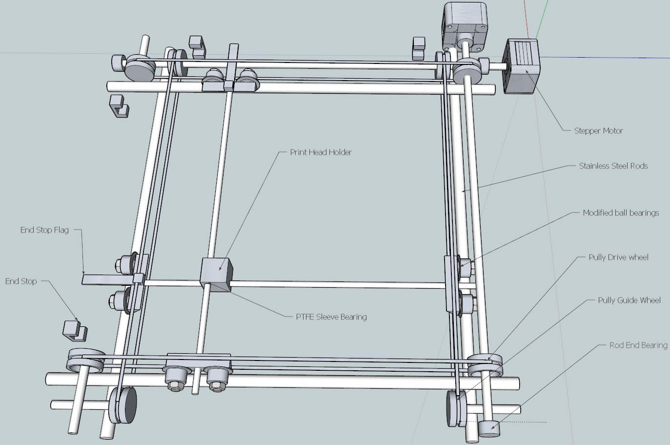
TandemB (Shield)
This second concept can be thought of as a 2D cousin to the delta robot. Again, two rods are jointed at an elbow with a bearing. However, the ends of the rods furthest from the elbow stay a fixed distance apart and instead move forwards or backwards to allow the elbow to sweep the ‘shield’ shaped build area. Rather than a rack and pinion setup as used for TandemA, this setup would use a belt or wire pulley system. Although a threaded rod or lead screw setup would also work, the much larger moment of inertia of the rods would likely reduce the maximum acceleration rates achievable by a considerable amount.

Note that although the image above shows rods used for the ‘arms’, any shape or material will work provided it is stiff enough.
The video below again gives an example of the movement.
Advantages of TandemB
- Again, both motors work in tandem to move the elbow joint in the conventional X/Y-axis directions with the exception of very specific arcs.
- Reduced part count, moving mass and total belt length, which reduces backlash, over an equivalent (CoreXY or ultimaker style) movement system. Can be built with only two smooth rods if the arms are replaced with other materials.
- Larger build area than TandemA and also does not suffer from the same non-linear flexing of its arms as they are at a fixed ‘extension’. Further discussion later.
- Build area can be isolated from all stepper motors, allowing a high temperature enclosure to reducing warping when 3D printing.
- Alternatively, the build area could be located in an unenclosed space away from the bulk of the machine for easy viewing, part extraction and extruder servicing.
- Only two rods need to be aligned in parallel in total for both the X and Y-axis.
- Both the X and Y-axis have the same steps/mm and mover linearly in the Y direction, simplifying calibration.
Disadvantages of TandemB
- Relies on computationally intensive movement calculations for Atmel AVR based microcontrollers, but again, likely not as bad as a delta due to being in 2D.
- Large horizontal footprint relative to actual build area.
- Careful management of the Bowden cable/wire harness to the tool head is needed to prevent changes in the vertical (z-axis) loading and the resulting flex in the z-axis.
- Possibility of the tool head oscillating in the Z-axis direction during rapid movements forwards and backwards. Further testing needed to see if this is really a problem.
- Possibility of a high wear rates on the linear bearings. This will likely limit the total tool mass to laser cutting/engraving or 3D printing with a Bowden extruder system.
In order to overcome the last three problems outlined above there is a third option which sacrifices maximum acceleration speeds in exchange for rigidity in the z-axis.
TandemC (Box)
This design is the same as TandemB, but with the addition of a stiffening crossbar to prevent flexing in the Z axis direction. This crossbar reduces the available build area to the green square shown below and also requires that the smooth rods are lengthed.

TandemB mockup made in sketchup with sketchyphysics.
Advantages of TandemC
The same advantages as outlined for TandemB with the addition of:
- Provided a large enough rod diameter is used, and if each axis was driven by a lead screw, then this setup could be rigid enough in the Z-axis for light milling duties and heavier tool heads than that possible with TandemB.
Disadvantages of TandemC
- Higher moving mass and part count than TandemB due to the addition of the crossbar, its linear bearings and mounts. The maximum acceleration will therefore be lower. There would also bow be a need for precisely parallel bars to prevent jamming, which is not true for TandemB.
Again, you can find a sketchup copy of these designs here.
Discussion
Of the three ideas I think TandemA would be the most rigid in the X and Y plane and the most light weight, and therefore the fastest. However, as mentioned above it will also suffer from a deflection in the x-axis due to the bending of the rods and play in the linear bearings. Some back of the envelope calculations (end loaded cantilever beams) suggest that the deflection expected in Z axis at full extension for a 6mm diameter, 250mm long stainless steel rod is in the order of 0.5mm for a 250g load placed at its end. Needless to say this is quite large and does not even take into account the play in the linear bearings. Even if you increase the rod diameter to 10mm, which now makes them quite heavy, you would expect a deflection greater than 0.07mm. The problem only gets worse if you try to increase the already small build area by making the arms longer.
Solving this deflection problem is not as simple as adjusting the bed angle either as the deflection is not linear. It could be possible to adjust for this deflection by tieing the z-axis position in firmware to the level of arm extension or just by rotating the whole device by 90 degrees so that the arms do not need to fight gravity. However neither solution is idea. Therefore, this might limit the TandemA design to applications where tight tolerances in the Z axis are either not required (such as engravers?) or only where very light loads are placed on the rods. Really, testing is needed to know for sure.
Note that the same deflection problem exists for the TandemB design, but because the arms are at a fixed ‘extension’ once the tool hight is calibrated it should no longer be a problem.
Equations of motion
The equations of motion for TandemA design can be found here, as they should be the same as for the polargraph design. The maths the TandemB and Tandem C designs, which are both identical in this respect, are outlined below using the schimatic shown.

In order to move the ‘pivot tool’ to a given position ( x, y) , the movement required on the A and B side is described by the following equations:

Where the x-axis movements for A (Ax) and B (Bx) are irrelevant as they are fixed at a given distance apart while the y-axis movements are a result of the parallel bar separation distance (S, where q = 1/2*S), arm length (r) and desired x and y position. I have made a spreadsheet where its possible to play around with the numbers and you can find that here.
I intend on building a TandemB to see just how stable it can be in the z-axis during rapid direction changes. If anyone has advice on how to implement the above motion equations into firmware that is compatible with RAMPS V1.2, or if you just have any other thoughts or comments regarding these concepts I would love to hear from you.


What if in the TandemA version you put the motors at 90deg’s? so one at the back like in the diagram above and the other off to one side?
Hi Gordon
Thanks for the interesting idea. However I believe that moving the stepper motors around will have no effect for the TandemA setup. This is because the two arms can pivot (yaw) and so are already, in a sense, 90degrees apart. To put it another way, imagine taking the image of the TandemA in the post above for a top down perspective and rotating it by 45 degrees. The two motors would now be 90degrees apart with respect to the horizontal, but not nothing has otherwise changed.
Pingback: Construction of TandemB Prototype | Capolight Electronics Projects.
What about using tandemC as the XZ axis, which would allow you to put a gravity-assist counterweight onto the cross bar.
This should work fine but would likely negate the speed advantage of the original tandem setup. Although it may be an attractive option if you want to use less smooth rods than an equivalent design. Another option is to rotate the printer 90 degrees and print on a vertical print surface. However, unless the print head mass was precisely balanced you would still see problems with stability during rapid direction changes. I am working on this problem at the moment.
As for a counterweight, rapid acceleration may cause the counter weight to lag behind the arm movements which could cause problems. I am not sure if a counterweight would even be needed as the total weight of the arms and print head is fairly negligible compared to the torque provided by the steppers. Although I may give it a try and see what happens.
Pingback: Modifying Marlin Firmware to work with a TandemB | Capolight Electronics Projects.
I just started prototype with a similar kinematic (but with modifications – my mathematical smoothing rods bear to center, that gives ability to shorten arms size)
Details here:http://forums.reprap.org/read.php?178,666239
I just started prototype with a similar kinematic (but with modifications – my mathematical smoothing rods near to center, that gives ability to shorten arms size)
Details here: http://forums.reprap.org/read.php?178,666239
Looks great! I will be interested to see how stiff you can get this setup in the z-axis. If nothing else it makes for a very compact penplotter.
I look forward to seeing how your project progresses.
Cheers,
Richard
Pingback: Leads For Contractors by Dr. Karl Ruegg » Construction of a TandemB Prototype