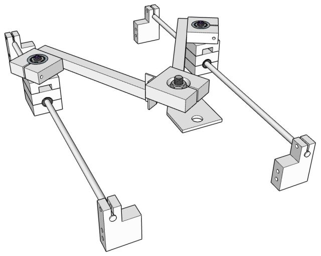
In a previous post I proposed the idea using an unconventional kinematic system to translation movements in the x and y axis. This idea, which was dubbed ‘Tandem’, is similar to that of a delta robot with the key difference being that rather than operating in three dimensions (X, Y and Z), it is restrained to only two (X and Y). A mockup of the ‘TandemB’ style kinematic system can be seen here. In this post I cover the construction of a ‘TandemB’ design which will be used for further experimentation.
CAD Drawings
The sketchup models shown previously (available here) were modified slightly and used as a basis for the design. The biggest change made was the addition of angled aluminum extrusion for the ‘arms’ as this simplified construction and is actually much lighter and stiffer than a 6mm stainless steel rod.
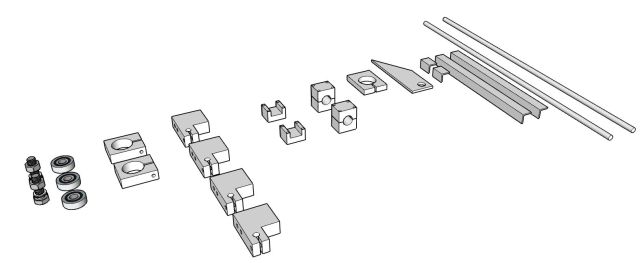
Each different part was arranged and dimensions added in order to make up a set up blueprints which were used for the construction.
The material chosen for construction was a 14mm thick hardwood plank simply because I happen to have this spare. Below you can see the parts needed for the x and y axis which were cut from this plank using hacksaw and then drilled out with a drill press. After a few iterations the parts came together fairly quickly.
Construction
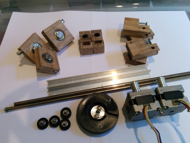
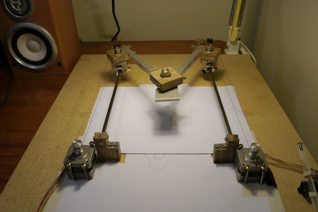
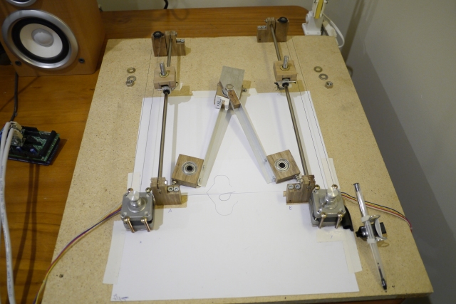
Its interesting to note that other than the bearings, screws and M8 bolts, all the other metallic parts shown were scraped from old printers and pen plotters. I assembled the parts on a flat test board which I will use for now until I can work out the changes need to firmware to drive it correctly.
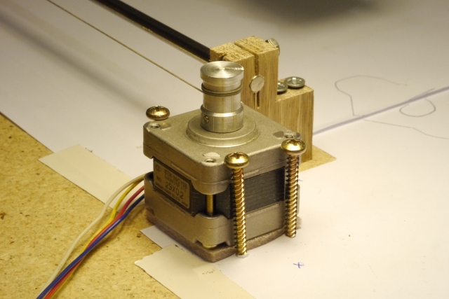
In more detail, the stepper motors are driven by a RAMPS 1.2 setup and have a 12mm spindle attached that moves a fine braided wire. This wire was also scrapped from a pen plotter. The wood screws shown below are just holding the stepper motor in place and allow for slight adjustments to its position and angle.
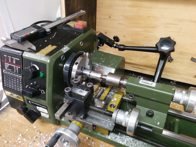
The wire spindles were turned down on a small lathe I have access to at work from 15mm aluminium bar stock. Each spindle then had two machine screws added to act as grub screws. I suppose something like these spindles could also be bought from an online store, but this was the fastest option available to me.
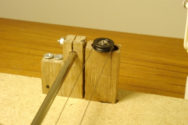
Freewheeling bearings that act as guides for the wires are located on posts at the opposite ends of the board to the stepper motors.
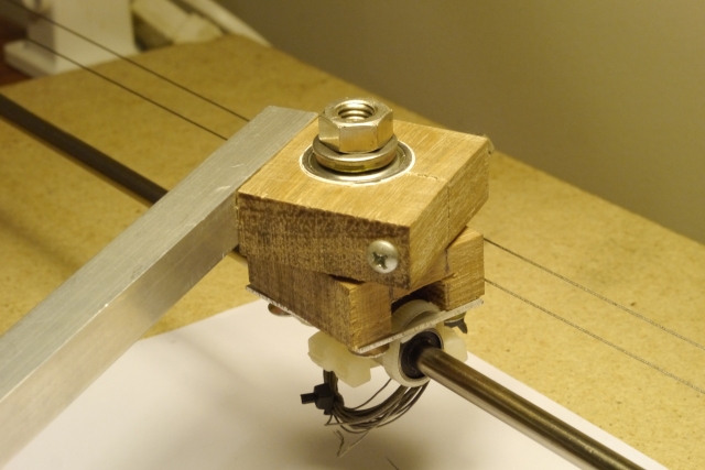
The pivoting sections each slide on the smooth rods using two LM6UU bearings. In the original design I had these bearings sandwiched between two pieces of timber. However I quickly found that this restricted their movement too much, leading to jams. This was fixed by replacing the timber with an aluminium plate and using the cable tie method instead.
I had also only planned on using a single 608ZZ bearing for each pivot point. However, due to a large amount of play in the bearings when used in this way I ended up using two bearings for each pivot as this made the arms much more rigid. Thankfully, due to the timber being 14mm thick and the bearings being exactly 7mm thick, no changes were needed. With a total of six 608ZZ bearings the arms are now stiff enough that the ‘TandemC‘ design may not be required for use with a 3D printer. However, more testing is needed to tell for sure. The holes for the bearings came out slightly oversized after drilling and so rather than compressing the wood further with the screw, which risks it cracking, I added some electrical tape to each bearing to bring its outer diameter up to the right size. This is something I should also have done for the smooth rod mounts as they did end up cracking their holding posts.
Below is a view with the arm removed off its posts and flipped upside down. One smooth rod is longer than the other because they are only what I had on hand.
In order to test out the movement of the arms with the stepper motors I used a simple sketch written with the AccelStepper library. The sketch shown in the video below has the two axis moving to random positions at random speeds using something similar to the ‘Random.pde‘ example sketch.
Note that the AccelStepper library allows a maximum of 4000 steps per second for both axis combined and so I have had to use full stepping, as opposed to microstepping, in order to get a reasonable movement speed. This is far below the ~16,000 steps per second you would normally see with a RAMPS set up and leads to very noisy movements that are then made worse by the mounting board acting as a soundboard.
The next step is to now find a suitable firmware that I can modify in order to add the reverse kinematics described in the previous post. Marlin firmware has been suggested as the simplest choice due to its level of segmentation, while Teacup has also been suggested due to the readability of its code. Unfortunately, after spending quite a few hours looking over the code for both I am no closer to understanding how either works due to my non-existent programing skills.
If anyone is able to help with adding ‘Tandem’ support to any RAMPS compatible firmware it would be greatly appreciated!


Pingback: Thought on this unusual XY axis concept? | 3D PrintNerd
Hi Richard,
I had the exact same idea that you had. Funny that I’m also a materials engineer. I want to help you with your programming issue. I don’t know how to start a private conversation, but I would like to have someone to work with. I also have some hardware points for you.
First software:
In Marlin the section you want is this:
#ifdef DELTA
void recalc_delta_settings(float radius, float diagonal_rod)
{
delta_tower1_x= -SIN_60*radius; // front left tower
delta_tower1_y= -COS_60*radius;
delta_tower2_x= SIN_60*radius; // front right tower
delta_tower2_y= -COS_60*radius;
delta_tower3_x= 0.0; // back middle tower
delta_tower3_y= radius;
delta_diagonal_rod_2= sq(diagonal_rod);
}
void calculate_delta(float cartesian[3])
{
delta[X_AXIS] = /* Magic math that turns the x and y axis into a single length value*/;
delta[Y_AXIS] = /* More of the magic that gives me my second length value*/
delta[Z_AXIS] = cartesian[Z_AXIS];
/*
SERIAL_ECHOPGM(“cartesian x=”); SERIAL_ECHO(cartesian[X_AXIS]);
SERIAL_ECHOPGM(” y=”); SERIAL_ECHO(cartesian[Y_AXIS]);
SERIAL_ECHOPGM(” z=”); SERIAL_ECHOLN(cartesian[Z_AXIS]);
SERIAL_ECHOPGM(“delta x=”); SERIAL_ECHO(delta[X_AXIS]);
SERIAL_ECHOPGM(” y=”); SERIAL_ECHO(delta[Y_AXIS]);
SERIAL_ECHOPGM(” z=”); SERIAL_ECHOLN(delta[Z_AXIS]);
*/
}
#endif
I have the magic math done. Simple solve of two circles given target XY. I need to go through the config and make sure there isn’t much to changing from pure delta to XY.
Next, the hardware.
Your setup has the delta machine radial component, but then also has a radial component associate with the end effector. I am going to use parrallel arms to ensure that the platform doesn’t have to have any added calculation.
Anyway, my version of this is listed at http://forums.reprap.org/read.php?2,469850 I’m using scanner beds because I pick them up for nothing. Might be too slow with the gearing, but we’ll see. I’d love to collaborate.
One more thing, those sketchup drawings are awesome. How do I learn to do that?
Hi Craig
Collaboration sounds like a great idea! I will be in touch by email.
One more axis, with some work and you have a 3D Printer 🙂
Pingback: Modifying Marlin Firmware to work with a TandemB | Capolight Electronics Projects.