
Last year I purchased a Cetus 3D printer which I have now been using off and on for 8 months. So far I have been very happy with the results.
Quick review of the printer
Positives:
- ~10 min assembly time.
- Extremely high print quality due to the use of linear rails and small nozzle sizes.
- Simple user interface.
- Can be modded for other uses such as a laser engraver.
- Can print in Pet-G and ABS without a heated bed if you use a glue stick prior to the first layer.
Negatives:
- Included software has limited slicing options. It does support 3rd party g-code but when doing so you no longer have a print time estimating.
- If no heated bed is used then you are limited to PLA or using large rafts.
- If you do purchase with a heated bed it is apparently quite slow to warm up and will only reach about 50C if your ambient temperature is low.
Overall I would highly recommend this printer to anyone needing a cheap high quality 3D printer in a small form factor.
After seeing this video by Marco Reps I have decided to upgrade my printer to include a heated bed. You can purchase an official heated bed for this printer but I want to roll my own more powerful version
DIY heated bed
Design objectives:
- Ability to monitor and set the print bed temperature
- Use a separate power supply to that used by the 3D printer so as to not overload it.
- Over-temperature protection independent of the temperature monitoring.
Parts list
- 8 * 2.74 Ohm 15W power resistors. These were just what I had on hand.
- High temperature PTFE coated wire
- 100 Deg C bi-metal switch for safety cutout
- Type-K thermocouple
- Omron E5CC temperature controller off AliExpress.
- Omron S8JC-Z15024C 24V, 6.5A PSU that I had on hand
- High current ‘Heated bed’ MOSFET break out board
Both the power supply and the switching MOSFET are overkill for this application but they are what I had on hand.
Modifying the heated bed
The power resistors were attached with two part epoxy as I did not have any thermal adhesive on hand. After many dozens of hours of printing this method appears to be working just fine. The resistors were wired up in a 4S-2P configuration so that the current draw from the power supply was around 4.2A for a total of 100W output.


In series with the input to the heated bed was placed the bi-metal switch so that in the even that it becomes stuck on full power it should still stay within a safe temperature range. Note that you can use a bi-metal switch as a method of temperature control on its own but that they tend to become stuck after a few thousand cycles. The MOSFET board was connected directly to the power-supply and switched with the relay output of the temperature controller. Note that the MOSFET board requires 12V to turn on and so I used a simple voltage divider to drop the 24V down to 12V.
The wires and the thermocouple were attached with capton tape. After remounting the bed I was pleased to see that it all just fits without needing to make any further changes.
Building the enclosure
Naturally, I wanted to print the enclosure on the Cetus and so I put something together in F360 which can be found here. It just fits the power supply, temperature controller and the MOSFET board. Plenty of veneration was also included. The CAD models for all the Omron parts were supplied by Omron on their website.
The temperature controller can be powered off mains AC or 24V DC. I decided to separate the high voltage mains from the low voltage components via a dividing wall and power the temperature controller off 24V. This design is made so that the whole Cetus 3D printer can safely sit on top of the enclosure which keeps the foot print nice and small.
Ever square mm of the printing area was used to print the enclosure, something that could not have been done without a heated bed.
Note that I initially printed the red lid first using the default Cetus print settings (and then ran out of filament) and the final result was pretty bad. After looking around on the cetus forums it looks like there is a problem with the included slicer when printing without a raft. To solve this I switched over to the excellent Simplify 3D slicer. After a few hours of adjusting the settings I managed to get great results. If your interested you can find a copy of my final settings here.


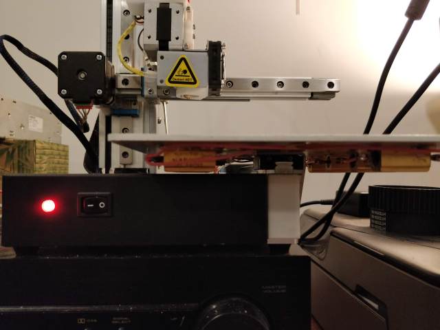
And finally the end result.
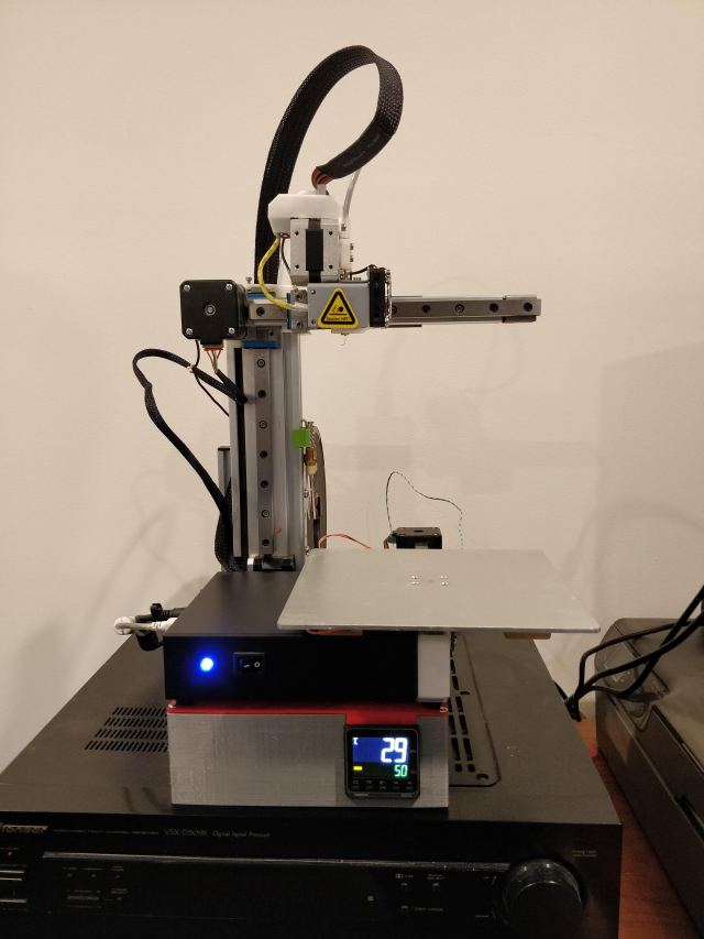
It takes around 4 minutes to reach 70C in an ambient temperature of 14C (it was cold in my garage where I timed it) which is a great improvement over the reported times of the stock heated bed.
If I was to repeat this whole exercise it would probably be a good idea to squeeze in a mains fuse some where just in case there was a fault with the power supply that its own internal protection didn’t catch. Also printing the enclosure in all one colour and including a cable drag chain would improve the overall look. Otherwise I’m quite happy with the end result

