I recently acquired an old Rikadenki pen plotter from a lab I work in and have decided to pull it apart to investigate how it works. It turns out to be quite unlike any of the Cartesian bots currently used by the DIY community.
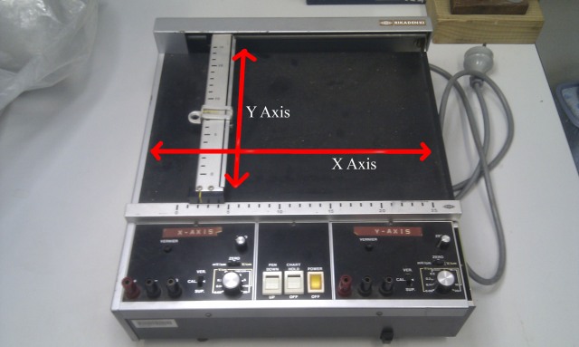
The pen plotter was originally used to plot magnetic hysteresis loops of magnetic materials onto paper using a pen fixed in a holder. A voltage from a scientific instrument was fed to each axis with the size and polarity of the voltage dictating the position of the pen.
Note that all images can be enlarged by clicking on them.
In the image above you can see the pen plotter with its x and y axis. The pen is fixed in the holder attached to the y axis and can move vertically only. The entire Y axis assembly can then move horizontally to form the x axis.
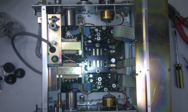
With the pen plotter turned over and its base removed the internal electronics can be seen.
It appears to be quite old in its design. As I dont have an electrical engineering background I didnt attempt to repair its existing electronics and so they were removed.
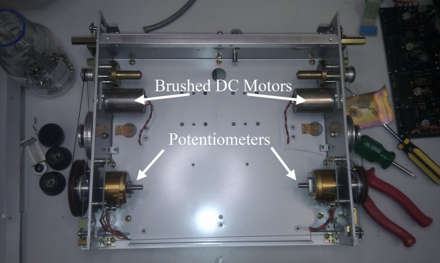
With the electronics removed two brushed DC motors and two potentiometers can be seen, one for each axis.
A thin gauge wire is used to move each axis. The potentiometers are also connected to the motors and geared such that a full movement of an axis from one end to another results in 1 full rotation of the potentiometer. It appears the potentiometers were used as position feedback. Each axis slides on a stainless steel shaft with out the use of bearings.
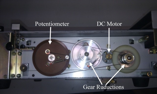
Looking side on these gear reductions can be seen more clearly.
Note the wire is guided by rotating spindles (seen in the bottom left) and spools around the drive wheel to ensure it doesnt slip. Springs are used to maintain tension on the wire where they are fixed to the centre of some of the hubs.
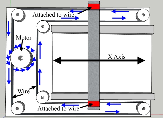
The path of each of the thin gauge wires, one for each axis, is hard to see in these images so I have tried to draw it schematically in sketchup. Note that the actual path in the pen plotter differs, but the idea is the same. This is the x axis.
When the motor turns it pulls the wire through a series of rotating guides to form a continues loop. The whole y axis assembly (the vertical grey rectangle in the image) is attached to the wires at the red points and is then moved left or right depending on the direction of the wire.
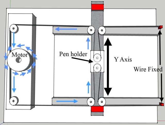
Below is the Y Axis.
When the y axis motor turns it pulls on the y axis carriage from the top of the image while also letting out wire for the carriage at the bottom of the image. This causes the y axis to move up, or down if the motor direction is reversed. If the X axis moves the whole y axis moves to the left or to the right. However, the y axis carriage does not move in the vertical direction as the y axis motor is stationary and so wire is pulled in and let out from the right side of the image where its fixed.
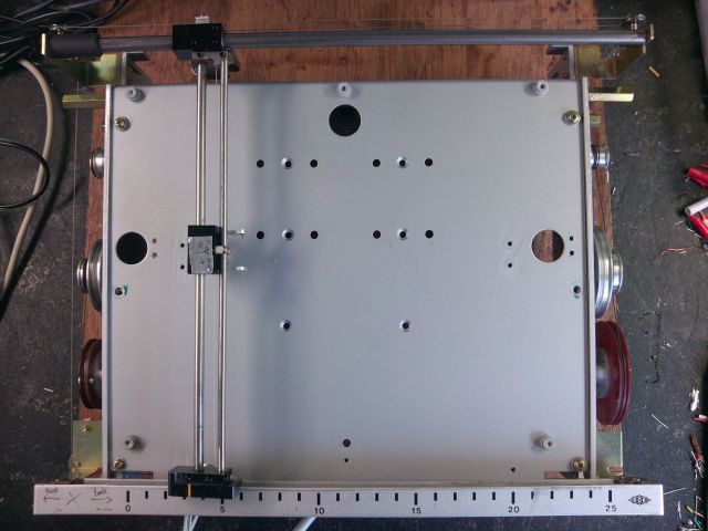
Here is one last higher quality photo with more parts removed.
Needless to say the movement of the x and yaxis is a lot more complex than a typical DIY belt driven 3D printer. However this complexity does have its advantages. For example, I imagine wire bought in bulk could be far cheaper than timing belts. Also DC motors a lot easier to find/buy than stepper motors. Perhaps of most interest though is the ultra low weight of the x and y assembly which could allow for very fast direction changes.
The next step is to put a H bridge together with an arduino and see if this pen plotter can be brought back to life.


It is similar to this http://maukcc.blogspot.com.au/2011/12/cartesio-update-v04.html
Thanks for the link, I hadn’t come across that particular blog.
Pls i want pen plotter driven by dual h bridge and arduino schemetics pls send me
Thank you for this, inspired me to make a 3d printer: https://www.youtube.com/watch?v=JFOXgfbH_gM
What was the wire made from (and where can I get some?)
The wire appears to be a braid of stainless steel only a few millimeters thick. It is very flexible while also being very stiff, which aids in the precision of the plotter. I am not sure where you are located, but if you are in the USA then perhaps try the following link.
http://www.mcmaster.com/#standard-wire-rope/=sed9d4
I will be sure to keep an eye on your blog.
Cheers.
Pingback: RichRap Releases Sli3DR Source Files - 3D Printing Industry
Pingback: RepRap Alchemist RichRap Shares Sli3DR 3D Printer design files up on Youmagine, Github #3DThursday #3DPrinting « adafruit industries blog
Pingback: Bootstrapping a pen plotter to make a 3d printer | Capolight Electronics Projects.
Dear Rechard,
I have gone through the simple diagrams of your blog. I found them useful to explain to the students. I am writing a book on 3D printers. I need your permission to include these diagrams in my book. Please let me know.
Dear Prof. Pandya
Please feel free to use any diagrams contained within this blog for your book so long as the appropriate credit is given. My details can be found below.
https://www.linkedin.com/in/richard-parsons-b421a330/
Regards,
Richard.